Huling Halik ni Physics

    Dalawang taon nakikipaglaban ng puyat matapos lamang ang Edmodo at maipasa sa tamang oras.

     Naaalala ko pa noong una kong gawin ang unang Edmodo na pinagawa ni sir. Submit it before 12:00 PM, parang wala lang ang relax pa noon sap ag-aakalang madali lang ang lahat, akala ko lang pala akala ko wala akong magiging problema yun pala mali ako. 11:55 PM tapos ko nang gawin yun sa wordpress kinakabahan na ako dahil ayaw magpublish noon 5 minutes nalang deadline na ‘di ko na alam gagawin ko ‘di ko alam kong saan ako nagkamali ginawa ko naman ang lahat ng tama sa pagkaka alam ko pero wala parin. Nagpatulong na ako noon sa classmate ko at sa kabutihang palad sa wakas na published din.

   Pero hindi doon nagtatapos ang problema dahil pagkatapos mong I published ay kinakailangan mo din itong I turn in sa Edmodo at ilagay ang link doon paa Makita ng guro naming. Akala ko isang pindot lang ayos na, ok na ang lahat pero nakailang pindot na ako wala paring nangyayari. Ayaw magpublished at nagkakaproblema sa email. 11:59 nawawalan na ako ng pag-asa na maipapasa ko sa tamang panahon. Kaya nagpasya akong kausapin na si Sir Lex at sinabing kong maari I screenshot ko muna ang gawa ko at isend sa kanya sa facebook dahil ayaw talaga makisama ng Edmodo sa akin.

    Physics, Edmodo at WordPress tatlong bagay na nagpapaalala sa akin na hindi lahat ng bagay nagagawa ng madalian, kong gusto mo itong matapos sa takdang oras kinakailangang paglaanan mo ito ng sapat na oras at atensyon dahil hindi lahat ng bagay na akala mo madali ay madali talaga minsan kong sino pa yung naiisip mong madali ay yun pa ang pinakamahirap gawin.

mararanasan mong:

Maghanap ng bagay na itinago ng iba.


magbato-pulot ng bola malaman mo lang kung gaano ito kabilis.


Gumawa ng catapult at pataasan at malayuan kayo kung saan ito makakarating.


Gumawa ng hindi lang basta-bastang parol dahil lalagyan mo ng ilaw. Very electronics.


   titigan sa salamin malaman lang ang distansya nito.

At marami pang ibang activities.


 Physics ang isa sa nagparanas sa akin na matulog ng 3:48 AM dahil ang hirap-hirap gawin at isa pa hindi ako magaling sa math. Lahat ng bagay prinoproblema naming maging ang nakasabit na picture frame, bilog na bola, salamin, at iba pa. Andaming activities na ipinapagawa sa amin ni sir aaminin ko na minsan nakakapagod din, nakakasawa at ang hirap pero kapag nandon kana ginagawa mo na marerealize mong hindi naman talaga nakakapagod at nakakasawa, oo mahirap pero makikita mo nalang ang sarili mong nag-eenjoy sa mga activities na ginagawa nyo. Sa physics para kaming bumalik sa junior high dahil kahit grade 12 na kami parang sinundan kami ng basic electronics, isa  sa pinakamahirap na subject noon sa junior high.

   Sa huling buwan sa maniwala kayo man o hindi mamimiss ko ang physics subject pero wag kayong mag-alala dahil parang may nasabi si sir na may physics din sa college, ayaw akong pakawalan.

  Huling kanta, huling tawa, huling asaran, huling “bes papel mon ah daras! agtest/quiz tay physics!”, huling “pakopya notes mon ah momshie”, huling “yieeeeeeehh”, huling “shet jay Gtech ko!”, huling requirements.

At higit sa lahat mamimiss ko ang mga classmate kong akala mo takas sa mental.


119688591_1744411732523902_1857535963_o19859237_1546724772024424_263518892_o24131310_1539110469498229_4071411806743211343_n24296346_1539110392831570_5816561932683345828_n (1)28584694_1850452068586534_537412733_ocafe uno (2)IMG_0051IMG_0065IMG_0101IMG_0266IMG_0269IMG_0320IMG_5931IMG_8906IMG_20151217_093922IMG20180301150509IMG20180301151016IMG20180301152208IMG20180301152737received_1810302435667509received_1810303299000756received_1810307775666975

physics12socrates now signing out.

Your not the only one

Dual Nature of Light

Sometimes it behaves like a particle (called a photon), which explains how light travels in straight lines. And sometimes it behaves like a wave, which explains how light bends (or diffracts) around an object.

xbhcbhbjhdfkjc

NEWTON (1643-1727)

Image result for isaac newton

States that light is a article. It can reflect or refract. His “Principia” first published in 1687.

One year after the Italian Natural Philosopher Francesco Grimaldi’s work on diffraction was published Sir Isaac Newton bought his first prism in 1666.

The image below is the crucial experiment of Newton.


Diagram showing white light split into a spectrum by one prism, and recomposed into white light by another prism.

Newton passed a beam of white light through two prisms, which were held at such an angle that it split into a spectrum when passing through the first prism and was recomposed, back into white light, by the second prism (as shown in Figure 3.1). This showed that the color spectrum is not caused by glass corrupting the light. Newton claimed this was a ‘crucial experiment’

He claimed that Grimaldi’s diffraction was simply a new kind of refraction. He argued that the geometric nature of the laws of reflection and refraction could only be explained if light was made of particles, which he referred to as corpuscles, since waves don’t tend to travel in straight lines.

After joining the Royal Society of London in 1672, Newton stated that the 44th trail in a series of experiments he had previously conducted had proven that light is made of particles and not waves.


CHRISTIAN HUYGENS (1629-1695)

Image result for christiaan huygens

He states that light is a wave.

Dutch physicist, Christiaan Huygens, believed that light was made up of waves vibrating up and down perpendicular to the direction of  the light travels, and therefore formulated a way of visualizing wave propagation.

This became known as ‘Huygens’ Principle’.  Huygens theory was the successful theory of light  wave motion in three dimensions. Huygen, suggested that light wave peaks form surfaces like the layers of an onion. In a vacuum, or other uniform mediums, the light waves are spherical, and these wave surfaces advance or spread out as they travel at the speed of light. This theory explains why light shining through a pin hole or slit will spread out rather than going in a straight line.


THOMAS YOUNG (1773-1829)

the double slit experiment

BBVA-OpenMind-Augusto-Belendez-Thomas-Young

He convincingly demonstrated the wave nature of light –contrary to the ideas of Newton who believed light was composed of a stream of particles– through the double-slit experiment, known today as Young’s light-interference experiment.

His experiment is considered to be one of the most beautiful experiment in physics and most favorite experiment of light.

With this experiment Young challenged the theories of Isaac Newton and proved that light is a wave, because light suffers the phenomenon of interference that is typical of the waves. When the waves emerging from two narrow slits are superimposed on a screen placed at some distance parallel to the line connecting these slits, a pattern of bright and dark fringes regularly spaced appears on the screen (interference pattern). This is the first clear proof that light added to light can produce darkness.

BBVA-OpenMind-Augusto-Belendez-Thomas-Young-3


ALBERT EINSTEIN (1879-1955)

he observed the photoelectric effect. But later in 1921 when he explained it.

According to him light is a particle. color is determined by the wavelength it emits.

Light is considered particle (because of the photoelectric effect) and wave ( because of the double slit experiment).


DAVIDSON

He duplicated Young’s double slit experiment using crystals proving de boyle’s theory.


In our lesson in diffraction we conducted an activity

I. Materials

  1. CD or DVD
  2. Cutter or blade
  3. Laser

II. Objectives

  1. to observe what will happen to the light.
  2. Actual experience of the Double slit experiment

III. Procedure

  1. prepare all the materials.
  2. remove the label of the CD or DVD
  3. Place it on the wall at least 1 ruler appart
  4. point the laser to the CD
  5. Observe

IV. Documentation

After performing the activity there is a equation you need to know.

jdfvdfjv


I’m straight PROMISE!

REFRACTION OF LIGHT

-Bending of light

-Light will only bend at a certain angle.

-it is generally known as Snell’s Law which governs the behavior of light rays as they propagate across a sharp interface between two transparent dielectric media.

In refraction of light we tackle two lenses the

  1. Double convex (Converging)Image result for parts of lenses
  2. Double concave (Diverging)

Image result for parts of lenses


Lets discuss first about the Double Convex Lens

We will try to investigate the method in drawing the ray diagrams for objects placed at various locations in front of a double convex lens. In order to do it right we need to recall the three rules of refraction for double convex lens.

  1. Any incident ray traveling parallel to the principal axis of a converging lens will refract through the lens and travel through the focal point on the opposite side of the lens.
  2. Any incident ray traveling through the focal point on the way to the lens will refract through the lens and travel parallel to the principal axis.
  3. An incident ray that passes through the center of the lens will in effect continue in the same direction that it had when it entered the lens.

here how it looks like

As you can see on this image there are five incident rays with their corresponding refracted rays. But we only need two incident rays to determine the image location since it only requires two rays to determine the intersection point. Even though we only need two rays it would be better to include 1 ray to check the accuracy of our rays.

Here are the step by step method in drawing a ray diagram for double convex lenses.

  1. Pick a point on the top of the object and draw three incident rays traveling towards the lens.

2. Once these incident rays strike the lens, refract them according to the three rules of refraction for converging lenses.

3. Mark the image of the top of the object.

4. Repeat the process for the bottom of the object.

After practicing it a couple of times it will be easier to draw now. You thought it will be the end? Your wrong after mastering it we need to make a ray diagrams on different places.

  1. ray diagram for objects located in front of the focal point.
  2. Ray diagrams located at the focal point


Double Concave Lens (Diverging)


Image result for diverging lens

There are also rules in drawing ray diagrams in double concave lenses

  1. Any incident ray traveling parallel to the principal axis of a diverging lens will refract through the lens and travel in line with the focal point (i.e., in a direction such that its extension will pass through the focal point).
  2. Any incident ray traveling towards the focal point on the way to the lens will refract through the lens and travel parallel to the principal axis.
  3. An incident ray that passes through the center of the lens will in effect continue in the same direction that it had when it entered the lens.

Image result for diverging lens

Here are the step by step methods in drawing a ray diagram

  1. Pick a point on the top of the object and draw three incident rays traveling towards the lens.

2. Once these incident rays strike the lens, refract them according to the three rules of refraction  for double concave lenses.

3.  Locate and mark the image of the top of the object.

4. Repeat the process for the bottom of the object.


This is how it looks like

we have an activity about this lesson and of course there are mathematics involved in this lesson.

it is not only drawing ray diagrams but also there are computations and equations to learn.

To obtain this type of numerical information, it is necessary to use the Lens Equation and the Magnification Equation. The lens equation expresses the quantitative relationship between the object distance (do), the image distance (di), and the focal length (f). The equation is stated as follows:

The magnification equation relates the ratio of the image distance and object distance to the ratio of the image height (hi) and object height (ho). The magnification equation is stated as follows:

At first i have difficulties in drawing the reflected rays I’m not sure of the rays i put if its in correct location or not.

Here are some problems you can use in practicing the mathematical part of this lesson.

  1. A 4.00-cm tall light bulb is placed a distance of 45.7 cm from a double convex lens having a focal length of 15.2 cm. Determine the image distance and the image size.

    You list down all the given data first.

    ho = 4.00 cm do = 45.7 cm f = 15.2 cm

    Identify the unknown quantities that you will solve.

    di = ??? hi = ???

    To determine the image distance, the lens equation must be used. The following lines represent the solution to the image distance; substitutions and algebraic steps are shown.

    1/f = 1/do + 1/di

    1/(15.2 cm) = 1/(45.7 cm) + 1/di

    0.0658 cm-1 = 0.0219 cm-1 + 1/di

    0.0439 cm-1 = 1/di

    d= 22.8 cm


    To determine the image height, the magnification equation is needed. Since three of the four quantities in the equation.

    hi/ho = – di/do

    h/(4.00 cm) = – (22.8 cm)/(45.7 cm)

    h= – (4.00 cm) • (22.8 cm)/(45.7 cm)

    h= -1.99 cm

2. 4.00-cm tall light bulb is placed a distance of 8.30 cm from a double convex lens having a focal length of 15.2 cm. Determine the image distance and the image size.

ho = 4.00 cm do = 8.3 cm f = 15.2 cm

 identify the unknown quantities that you wish to solve for.

di = ??? hi = ???

Solution:

1/f = 1/do + 1/di1/(15.2 cm) = 1/(8.30 cm) + 1/di

0.0658 cm-1 = 0.120 cm-1 + 1/di

-0.0547 cm-1 = 1/di

d= -18.3 cm

determine the image height by using magnification equation.

hi/ho = – di/doh/(4.00 cm) = – (-18.3 cm)/(8.30 cm)

h= – (4.00 cm) • (-18.3 cm)/(8.30 cm)

h= 8.81 cm

Every problem that you will do you need to compute for its percent error to check if your ray diagram and mathematical part is parallel to each other. In getting the percent error just remember this equation

DDDD


That’s all for the double concave and convex lenses.

Your not Real

Introduction of Speed of Light

Galileo was the first person to try to determine the speed of light but he was not successful to get the result accurately.

A Danish astronomer, Olaus Roemer in 1676 who first successfully measured the speed of light. It was 2.99792458 or 2.9×10^8 m/s.

If somebody ask you which comes first, thunder or lightning? what would be your answer? most of us will tell the lightning because we see it first than the thunder.

BUT actually they both comes at the same time! how?

When a lightning bolt travels from the cloud to the ground it actually opens up a little hole in the air, called a channel. Once then light is gone the air collapses back in and creates a sound wave that we hear as thunder. The reason we see lightning before we hear thunder is because light travels faster than sound (Wizkid, 2015).

Plane Mirror

Image result

The law of reflection states that the incident ray, the reflected ray, and the normal to the surface of the mirror all lie in the same plane. Furthermore, the angle of reflection is equal to the angle of incidence.

the location of the object in a plane mirror is the same

In this lesson we conducted an activity.

We need to prepare:

  1. Mirror (as much a possible without border for more accurate results.)28207978_1734071043279838_1540461206_o (1).jpg
  2. Ruler, Pencil, and Protractor 28170881_1734070999946509_380347665_o
  3. Pins28126619_1734071093279833_789815165_o

After preparing all the materials each of us are given certain angle to follow.

After you marked the angled line you need to carefully see at the eye level the pins and draw it on the reflected ray.

Actually were not 100% accurate of our result because there are a lot of factors that can affect it, 1st, if you use glasses or the mirror you use is not even. In this activity its not just a graphical presentation there also a mathematical way to see if you got all your graphical presentation right or how many percent error you commit.

We need to find LOST

L- Location

O-Orientation

S-Size

T-Type

  • If you draw a ray, parallel to the principal axis,   it is called P-RAY.
  • F-RAY, a line that passes through the focus
  • V-RAY, incident ray is equal to the reflected ray.


We also try to put two mirror in a right angle form and put a pin in the middle and see how many images are form on different angles.

θ                number of image formed

  1. 90º –                 3
  2. 60º –                 5
  3. 45º –                 8
  4. 30º –                 12
  5. 15º –                 24

There are equation for this activity

number of images= nnn

MIRRORS: Concave, Convex, Double Concave, Double Convex, Nano Concave, Nano Convex, Meniscus


CONCAVE MIRROR

Image result for concave mirror

Image result for concave mirror

in concave mirror if ray 1 is parallel to the p ray it will reflect on the focal. and if ray 2 is directly in the focal it will reflect parallel to the p ray. and if ray 3 is directly to the center it will reflect back.

in real life you can see this kind of mirror on a dentist office.

Image result for equipment for dentist

CONVEX MIRROR

  • Any incident ray traveling parallel to the principal axis on the way to a convex mirror will reflect in such a manner that its extension will pass through the focal point.
  • Any incident ray traveling towards a convex mirror such that its extension passes through the focal point will reflect and travel parallel to the principal axis.

Image result for convex mirror

After doing some activity like this picture above we also learn about the Mirror Equation and the Magnification Equation.

The mirror equation expresses the quantitative relationship between the object distance (do), the image distance (di), and the focal length (f). The equation is stated as follows:

The magnification equation relates the ratio of the image distance and object distance to the ratio of the image height (hi) and object height (ho). The magnification equation is stated as follows:

Here are some examples

  1. A 4.00-cm tall light bulb is placed a distance of 45.7 cm from a concave mirror having a focal length of 15.2 cm. Determine the image distance and the image size.

after drawing the graphical presentation you also need to compute it. using the equation stated above. so it goes like this.

ho = 4.0 cm do = 45.7 cm f = 15.2 cm
di = ??? hi = ???

1/f = 1/do + 1/di

1/(15.2 cm) = 1/(45.7 cm) + 1/di

0.0658 cm-1 = 0.0219 cm-1 + 1/di

0.0439 cm-1 = 1/di

d= 22.8 cm


hi/ho = – di/do

h/(4.0 cm) = – (22.8 cm)/(45.7 cm)

h= – (4.0 cm) • (22.8 cm)/(45.7 cm)

h= -1.99 cm

so after you get the answer you need to compute again. yes again. this time you need to know the percent error. how to do it?

DDDD.PNG

Soooo after how many activities we did i think we already mastered this lesson. We just hope there’s no more complicated problems.


Electrifying Christmas

Physics, Biology, Contemporary and English For Academic and Professional Purposes

Adding all this four subjects equals Electrifying Christmas Lantern.25299181_10208164495709889_760817223191486171_n.jpg

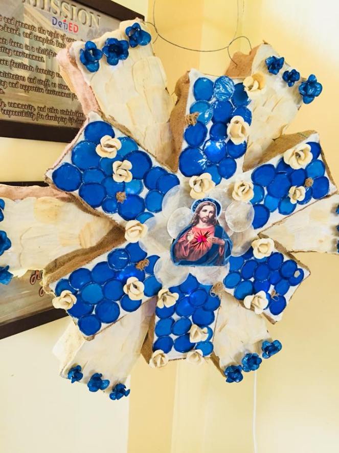
But making this masterpiece is not easy.  A lot of sleepless night have passed, bottles of Kopiko to keep us awake and a lot of snacks.

This is not just an ordinary lantern. We also put lights on it to be more beautiful and elegant.

This is a thematic project

  1. Physics – we are graded for the circuit
  2. Biology- for the domestic crops used in making the parol
  3. Contemporary- for the design of it, and
  4. EAPP – we will make a brochure of the lantern

Lets focus here on Physics. Let me explain to you the following 12

  1. Parallel
  2. Series
  3. Capacitor
  4. Resistor
  5. Transistor
  6. L.E.D
  7. Switch
  8. Transformer
  9. Voltage
  10. Power
  11. Electric Consumption
  12. Circuit diagram

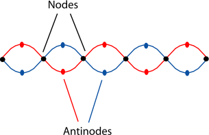
  1. Parallel- in our lantern we use parallel circuit.
    25360163_1695312690498964_114052275_n.jpgImage result for parallel circuit

In parallel circuit if one bulb blew out the others will still be working because there is still current flowing to the others because they are still in direct path from the negative to positive terminals of the battery. Parallel has two or more paths for the electricity to flow.  There are formula that you need to know, Ceq= C1+C2+C3. You just need to add all to know the sum.

2. Series- We also use series circuit in our lantern. its in the outer rays of the snowflakes. Unlike in Parallel, if one bulb blew out the whole circuit will not work since series circuit have only one path for the electricity to flow.This is how series looks like.

Image result for series circuit

    Mostly all houses uses Parallel connection in their house because its very hassle if one bulb blew out then all their lights will automatically shut down. Although we also use series connection in Christmas lights.

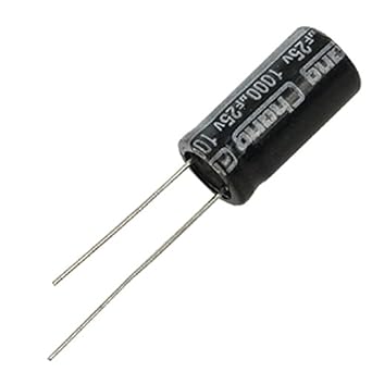
3. Capacitor- its a device that stores electrons. Basic capacitor is made up of two conductors separated by dielectric. The dielectric is either made of plastic, ceramic, paper, glass, mica or none. The capacitance is measured in Farads (F). 1 F= 6.28 E 18 electrons. In our circuit we only use two capacitors. we use electrolytic capacitor. If we remove a capacitor from our circuit the L.E.D will explode because capacitor acts as a regulator, so that the bulb will receive a desired amount of electricity needed.

Image result for electrolytic capacitor

4. Resistor- it is a device that limits, or resists current. The most common materials used in making it is carbon composition. Resistance can be measured in ohms.

25360163_1695312690498964_114052275_n.jpg

We use four resistors in our circuit a carbon composition resistor. made either by hot or cold molding from mixtures of carbon and clay binder. two 470Ω and two 10kΩ. Most resistors have fixed values. some can be controlled. when i was still in grade 10 we have basic electronics subject. Our teacher teach us how to compute the total resistance. this is how to compute it. you just need to look for the colors.

Image result for color resistor code

5. Transistor- we use two BJT type, NPN transistor.

Image result for npn transistorImage result for npn transistor

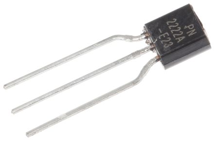
this is how it looks like. when no voltage is applied at transistors base, electrons in the emitter are prevented from passing to the collector side because of the pn junction. if a negative voltage is applied to the base things get even worse as pn junction between the base and emitter becomes reverse-biased resulting in the formation of a depletion region that prevents current flow. the use of transistor in a circuit is a simple switches. it conducts current across the collector-emitter path.

6. L.E.D- honestly we don’t use L.E.D in our circuit because we cant find color white thats why we buy a Christmas light and disassembled it
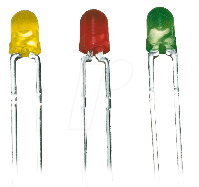
 Image result for LED.

there are 7 types of Light emitting diode (LED).

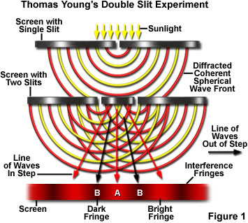
The light emitting section of an LED is made by joining n-type and p-type semiconductors together to form a pn junction. as the electrons combine with the holes, photons are emitted. well if we remove the LEDs the lantern will be boring.

7. Switch-  one requirement in making the circuit is using  two switches. we use Red button on-off 4 pin DPST boat rocker switch. by using switches we can control our lantern. we can easily manipulate the lights, we can turn on the parallel while we turn off the series or vise versa.

Related image

8. Transformer- work on the principle of electromagnetic induction. transformer are made of two or more inductors with metal core usually made of iron. in our circuit we really need to use transformer because we we do not, the whole thing will explode and be on fire. there are 4 parts of the transformer.

25383129_1694878333875733_442068893_o.jpg

  1. Primary winding/coil – coil connected to the power source.
  2. Secondary winding/coil – coil connected to the load. output coil of the transformer.
  3. Core- ferromagnetic material where the wires are wounded. its purpose is to increase the magnetic flux and to provide a medium.
  4. Bobbin- made of plastic materials, used to support the primary and secondary windings.

there are two types of transformer. Auto transformer and isolation transformer. the picture above is the isolation transformer.

9. Voltage-  pressure from an electrical circuit’s power source that pushes charged electrons (current) through a conducting loop, enabling them to do work such as illuminating a light. In brief, voltage = pressure, and it is measured in volts (V) (Fluke, 2018.) we use 9 volts because our circuit is just simple and small.

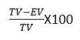
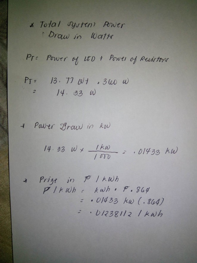
10. Power- Energy given in a certain amount of time, usually measured in watts. here are our computation of power consumption of our circuit. 25371101_1519488368170982_1383328577_o25371432_1519488388170980_1795194459_o

11.  Electric Consumption-  are the total amount of energy consumed by the circuit or by our lantern. This is often measured in Joules (J) or in kilowatts (KW) . Electronic devices consume electric energy to generate desired output (i.e., light, heat, motion, etc.).  here are our computation in electric consumption of our lantern. As you can see in our computation we also include the amount in peso consumed in using our lantern.

25383035_1519488401504312_1992510553_o

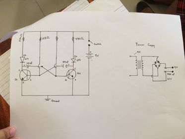
12. Circuit Diagram- used to give a visual representation of an electrical circuit. The pictorial style circuit diagram would be used for a broader, less technical audience. Before we make our lantern we need to submit first our circuit diagram to Mr. Supnet, our Physics teacher. He need to check it first. it looks so easy but honestly i almost throw my cellphone because of the app Icircuit. In here you can make a virtual diagram and you can check it if its working or not. this is very convenient because we don’t need to buy materials to in order to test it. 25360163_1695312690498964_114052275_n

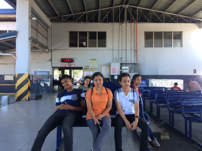
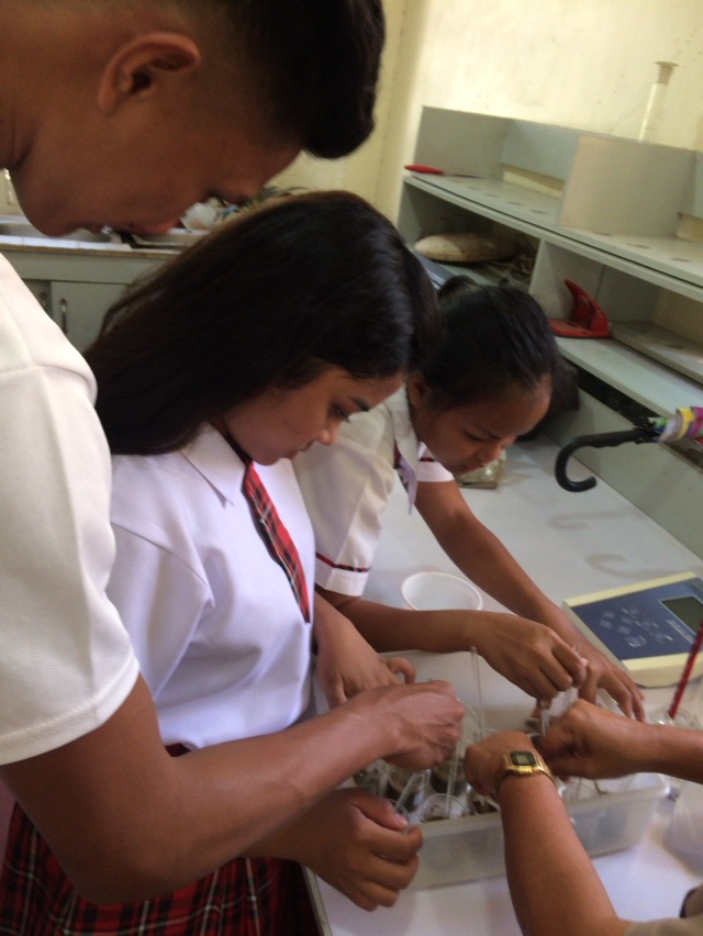
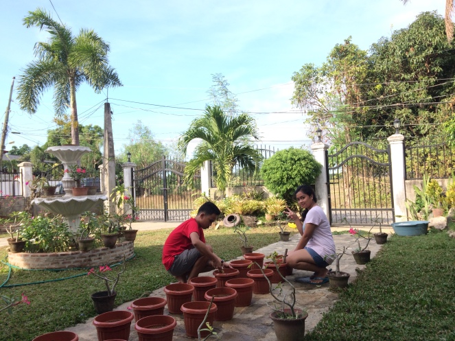
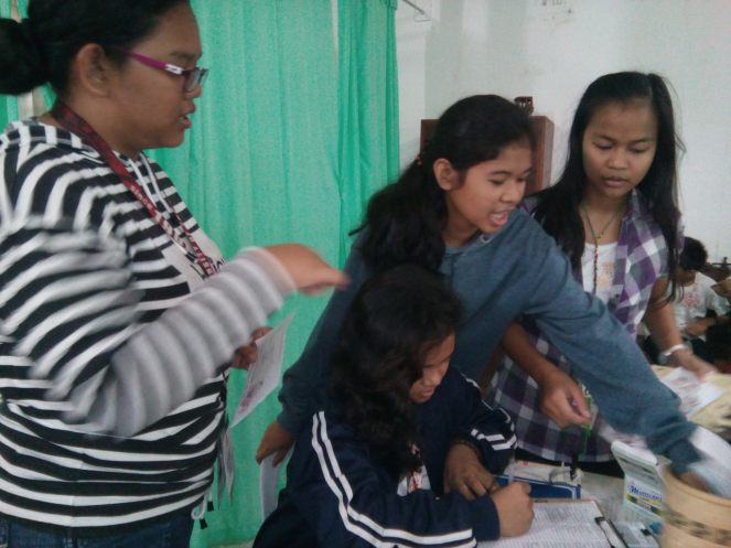
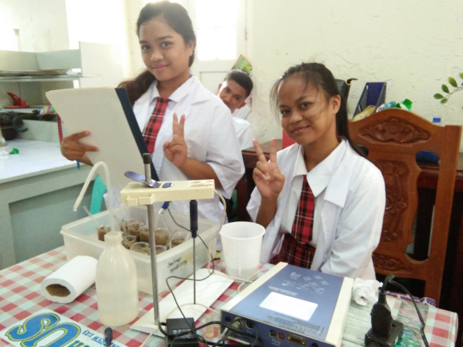
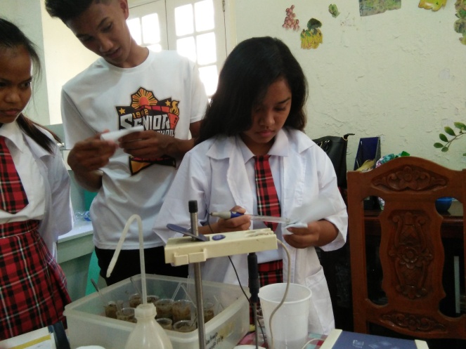
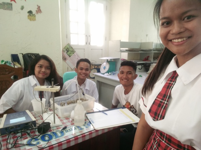
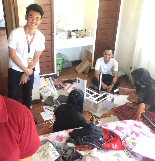
Here are our documentation in the making of our lantern. in chronological order.

Our group presenting our lantern to our four teachers.

26696373_1717776244919275_1868323324_n

Thank you!!

I would like to thank Mr. Alvin Pajo, our teacher in Basic electronic when i was still grade 10. Most of the information mentioned here are from his lessons and printed handouts he provided for us.

Connect

Coulomb’s law

   The magnitude of the electrostatic force of attraction or repulsion between two point charges is directly proportional to the product of the magnitudes of charges and inversely proportional to the square of the distance between them. The force is along the straight line joining them.

Electric field

E=F/qο

where E = electric field

F= force (N)

qo= test charge


Lets have some example

  1. A uniform electric field is directed downward. And has a magnitude of 5 N/C. Find the magnitude of -6C placed in its field.

Solution. F=Eqo

F=(5N/C)(-6C)

=-30N upward

2. Find the force experienced by the test charge

ui.PNG

a


You need to know this equation too.

Fe=kq1q2/r2

where k is constant which is 9×10^9

example problem

z

f

(r1)^2 = 2-x                 y+x=2

(r2)^2 = x                    y=2-x

9×10^9NC^2[(2×10^-9C)(1.0)/2-x] + 9×10^9NC^2 [(-3×10^-9C)(1.0)/x]

=18N/2-x + -27N/x = 0

=18Nx+ (-54N + 27Nx)=0

= 45 Nx-5.4N=0

=45Nx/45N = 54N/45N

x=1.2 N


Why the electron doesn’t fall from the nucleus?

An electron, unlike a planet or a satellite, is electrically charged, and it has been known since the mid-19th century that an electric charge that undergoes acceleration (changes velocity and direction) will emit electromagnetic radiation, losing energy in the process. A revolving electron would transform the atom into a miniature radio station, the energy output of which would be at the cost of the potential energy of the electron; according to classical mechanics, the electron would simply spiral into the nucleus and the atom would collapse.

death_spiral.jpg

Second Law

The second law of thermodynamics states that the total entropy can never decrease over time for an isolated system, that is, a system in which neither energy nor matter can enter nor leave.

After familiarizing with the first law of thermodynamics. We are now ready to take second law of thermodynamics and heat engines.

According to the first law of thermodynamics heat and work are mutually interchangeable.

2nd Law of thermodynamics gives the direction of flow of heat energy.

Heat engine is a device used for converting heat energy constantly into mechanical work.

THE SCHEMATIC DIAGRAM OF A HEAT ENGINE

schematic diagram

another

In this diagram you can see three parts which is the;

  1. Source or hot body
  2. Working substance is taken along the cycle of operations
  3. Sink or cold body

The working substance absorbs heat from the source transforms part of it into mechanical energy and the remaining parts are rejected to the sink.

The heat energy is never completely converted to mechanical energy that is, the efficiency of a heat engine is neve equal to 100 percent.

The equation for this is

η= Q1-Q2/Q1

there are four types of strokes

  1. Intake stroke
  • When the engine starts, the piston moves downwards in the cylinder because of which a region of low pressure is created in the cylinder above the piston.
  1. Compression Stroke
  • When sufficient amount of fuel is sacked into the cylinder the intake valve closes. The piston is forced to move upwards and as a result the fuel mixture is compressed to 1/8th its original volume.
  1. Power stroke
  • When the fuel mixture is completely compressed the spark plug produces an electric spark which ignites the mixtures. The petrol burns rapidly and produces an extremely large volume of hot gases. The pressure exerted by these products of combustion pushes the piston downwards with a great pace.
  1. Exhaust Stroke
  • When the piston has been pushed down to the bottom of the cylinder, the exhaust valve opens and due to the momentum gained by the wheel the piston is pushed upwards.

Four Stroke


ENTROPY

-represents the inevitable partial loss of an engines ability to convert heat energy into work. It is a state function measured in J/K.

ΔS=Q/T

ΔS=change in entropy

Q=heat

T=temperature in K

R= reverse process


ΔS =0 for Carnot engine

ΔS univ =0 for any reversible process


Carnot Engines and heat

-engine is system

-use heat transfer to and from engine to do work on surroundings

– “perfect” engine: no friction


Steps to Carnot cycle

  1. Isothermal expansion
  2. Adiabatic expansion
  3. Isothermal compression
  4. Adiabatic compression

To calculate the amount of work done by a heat engine you need to know this formula

W=Q1­­-Q2

W=work done by engine(J)

Q1=heat transferred in (J)

 Q2=heat transferred by (J)


After discussing all this facts about 2nd law of thermodynamics and heat engines we are now ready to answer all the questions in our activity.

Here are some of the questions. I hope this will help you understand more the concept of this lesson.


  1. A heat engine takes in 4500J of heat energy, then does 2750J of work. How much heat energy does the engine expel as waste?

Given:

W=2750J

Q1=4500J

Q2=?

Solution: W=Q1­­-Q2

2750J-4500J= Q2

Q2=1750J

  1. If 100 J of heat is added to a system so that the final temperature of the system is 400K, what is the change in entropy of the system?


ΔS=Q/T

= 100/400

= 0.25J/K

  1. If you know that the change in entropy of a system where heat was added is 40J/K, and that the temperature of the system is 200K what is the amount of heat added to the system?


ΔS=Q/T

40J/K=Q/200K

Q=8000J

First LAW

First Law of Thermodynamics must be conserved.

Energy can be neither created nor destroyed

Before anything else you need to familiarize with this equation.

ΔU=Q-W 

where Q is heat and W is work

The change in internal energy of a system will be equal to the energy transferred to or from the system as work. All are measured in joules (J).

There are Four types of Processes that can occur.

  1. Isovolumetric or Isochoric

-Any changes in energy is the result of heat transferres.

-No change in Volume

For example. A bomb calorimeter where a combustion reaction produces a change in temperature but the rigid walls result in no change in volume

isovolumetric.PNG

2. Isothermal 

-If there is no change in the temperature of the system, there cannot have been any change in the internal energy of the system since these 2 values are proportional.

isothermal.PNG

It means that any heat transferred into the system is used by the system to do work rather than increasing the internal energy of the system. A constant temperature. An ideal version of a car engine would use all its energy for work.

     3. Adiabatic

– If there is no heat transfer then Q=0 and ΔU= -W. It means that the internal energy of a system changes as a result of doing work on its surrounding or the surroundings doing work upon the system. No heat transferred. Internal energy is exclusively used for work.

adiabatic.PNG

4. Isobaric 

-A process in which pressure stays constant: ΔP = 0. For an ideal gas, this means the volume of a gas is proportional to its temperature.

isobaric


THERMODYNAMIC SYSTEM

System is a part of the universe that we want to study.

Boundary separates the system from the surroundings.

Surroundings is the rest of the universe.

There are three types of system

  1. Open System– both matter and energy can be move through boundary into and out of the system.

Open System.png

2. Closed System– only energy can move through the boundary into and out the system.

closed

3. Isolated System– neither matter nor energy can move through the boundary into and out of the system.

isolated

THERMODYNAMICS AND P-V DIAGRAMS

  1. Isothermal

o.png

There is an increase in pressure and the temperature is constant.  The curve under the curve is the work done. It is right to the left therefore it is negative.

2. Isovolumetric

i

Locked volume of the piston and add energy through heat. the volume is constant.

3. Isobaric

ivi.png

Pressure is constant.

4. Adiabatic

aida.png

Internal energy in a system can change by adding heat or Q or work.


Alas! It looks like Thermodynamics is very very very simple in the way i explain it above.

Reality sucks. I really have a hard time digesting all the concepts and the lesson itself. In this lesson we have an activity but we answer it by two’s. We solve different problems and so on. We have  hard time answering it because were not that fully familiar with it specially the four processes (Adiabatic, Isochoric, isothermal, and Isobaric).

Maybe our teacher notice that Jestoni and I are having a little problem with it that’s why he further explain it again for us and thankfully our teacher allowed us to discuss it to other groups and they contributed big help to us.

Even though we have a hard time answering it for us its very worth it specially when we finish answering the question and we got it right. Although we didn’t perfect the activity at least we did our very best to learn, to answer the question and got at least more than half the questions.

Doing physics in the future i hope there will still Flickers. Its very fun taking quiz using that app specially when teacher is going to reveal who got the correct answer and how many who answered the choices.

In physics you will always need to take down notes! why? because you will not get it correct and fully understand it without looking at your notes.

Here are some of the problems we encountered

23627092_1489159677826588_1982668154_o23659972_1489159617826594_1779901832_o23698735_1489159567826599_1021746583_o


23634129_1489171554492067_1149084388_o.jpg

Its a little bit complicated if your looking at it but as you step by step learned it you’ll find it easy.

I always laugh when people tell me that love is very complicated. Well i’m sorry PHYSICS is way more complicated but we don’t have other choice. We need to accept it.

I want you to be HOTTER

A lesson of the Zeroth law of Thermodynamics.

In this lesson our teacher gave us an activity to answer.

    Mr. Sahin and his family have moved to a new house. A heating system is installed in the house before hey move in. With the coming of winter, the house needs to be heated. So the family wants the heating system to be turned on so that they can meet their heating needs. About 25 minutes after the radiators are turned on and the house begins to be heated up, they suddenly realize that the house is not getting any warmer. When they check the boiler on their balcony, they find that the water has been depleted and the heating system has automatically stopped.

We are given sets of questions to answer here.

  1.  What is the possible problem?

-The heater suddenly stop working

2. Write down your hypothesis about the source of the problem

a. the water has evaporated and the heating system stopped

b. there must be something wrong with the istallation

c. there must be a water leakage

3. What can be done to solve this problem

a. Check the water

b. check all the connections if there’s wrong in installation


   After the Heater stop Mr. Sahin call in the Thermodynamic authorized service and explains to the technicians so that the source of the problem can be determined and solved. the technicians from the authorized service check the system and explained that there is no problem with the mechanical installation of the heater and also no problem with the plumbing in the house or the connections in the heating system installation. the technicians dwell on the fact that there is a significant reduction in the level of water in the boiler.

   By the observation of the technicians we eliminate number 2 possible cause of the problems which is the wrong installation of the heating system including plumbing connections. By this it makes my two hypothesis correct. one of them may be the reason why the heater stop. the technician mention about the low level of water and maybe there are leakage of water of evaporation.

   The technical service convey the problem at Mr. Sahin’s house to the company engineer. The calculations of the company engineer showed that all of the water in the boiler could not evaporate in space of 25 minutes and that the problem stemmed from another mechanism; this was conveyed to Mr. Sahin. The engineer said that there could be a problem in the plumbing infrastructure (in the hidden pipes) and that the water seepage could be coming from there.

  The heating system is turned on once again and the same problem occurs. when the water in the boiler is depleted, the water continues to fill up the tank. at this point the neighbors downstairs complains. The complaint is that there is water dripping down from the living room ceiling. Therefore understood that the seepage is in the pipes in the living room. An estimate is made as to from where in the living room the water may be dripping and Mr. Sahin has the repairmen pull up the flooring in the living room and the leak is found. It is seen from an examination of the area that a nail had been nailed into one of the pipes in the plumbing at the time the floor covering was laid out.

   We all know that the pipes were made of plastics and the nails are metal that’s why if you turn on the heater there will be a heat and both the pipe and nail will expand. and the water seeps between the pipe and nail


An Annoying Sound!

Standing Waves and Resonance

   Standing wave, also called stationary wave is a combination of two waves moving in opposite directions, each having the same amplitude and frequency. The phenomenon is the result of interference—that is, when waves are superimposed, their energies are either added together or cancelled out.

            Resonance is a phenomenon in which a vibrating system or external force drives another system to oscillate with greater amplitude at specific frequencies. Frequencies at which the response amplitude is a relative maximum are known as the system’s resonant frequencies or resonance frequencies.

There are two types of wave 

  1. Standing Waves– A standing wave pattern is a pattern which results from the interference of two or more waves along the same medium. All standing wave patterns are characterized by positions along the medium which are standing still. Such positions are referred to as nodal positions or nodes. Nodes occur at locations where two waves interfere such that one wave is displaced upward the same amount that a second wave is displaced downward. This form of interference is known as destructive interference and leads to a point of “no displacement.”          A node is a point of no displacement. Standing wave patterns are also characterized by antinodal positions – positions along the medium that vibrate back and forth between a maximum upward displacement to a maximum downward displacement. Antinodes are located at positions along the medium where the two interfering waves are always undergoing constructive interference. Standing wave patterns are always characterized by an alternating pattern of nodes and antinodes.

2. Traveling Waves -A mechanical wave is a disturbance that is created by a vibrating object and subsequently travels through a medium from one location to another, transporting energy as it moves. The mechanism by which a mechanical wave propagates itself through a medium involves particle interaction; one particle applies a push or pull on its adjacent neighbor, causing a displacement of that neighbor from the equilibrium or rest position. As a wave is observed traveling through a medium, a crest is seen moving along from particle to particle. This crest is followed by a trough that is in turn followed by the next crest. In fact, one would observe a distinct wave pattern (in the form of a sine wave) traveling through the medium. This sine wave pattern continues to move in uninterrupted fashion until it encounters another wave along the medium or until it encounters a boundary with another medium. 

Related image

    In this lesson we conducted an activity but i was not able to take a picture of it that’s why i just search online for the same activity.

Capture

in this activity as you increase the Hz the pitch increases too. h


rtrt.PNG

When you reach this Hz i’m sure you’ll kill the one whose playing it. Its really irritable.

Image result for nodes and antinodes

    At these points the two waves add with opposite phase and cancel each other out. They occur at intervals of half a wavelength (λ/2). Midway between each pair of nodes are locations where the amplitude is maximum. These are called the anti-nodes. 

APPLICATION IN REAL LIFE

Image result for standing waves applied in real life

Playing a guitar or violin 

   A guitar string has a number of frequencies at which it will naturally vibrate. These natural frequencies are known as the harmonics of the guitar string.  the natural frequency at which an object vibrates at depends upon the tension of the string, the linear density of the string and the length of the string. Each of these natural frequencies or harmonics is associated with a standing wave pattern. 

    The graphic below depicts the standing wave patterns for the lowest three harmonics or frequencies of a guitar string.